
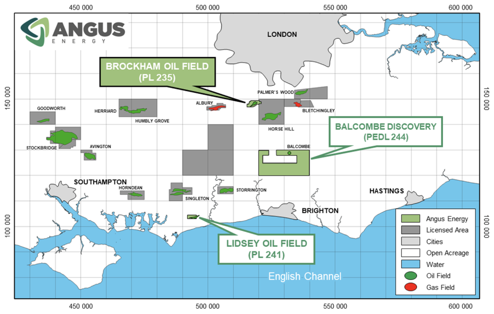
Angus operates 3 licences in the Weald Basin in southern England, containing the Brockham, Lidsey and Balcombe oil fields. Angus has not employed, and has no plans to employ hydraulic fracturing (“fracking”) at any of its operations in southern England.
Brockham Oil Field
Situated in the Weald Basin, the Brockham field was put back into production by Angus in June 2024.
- Licence
PL235 (Production Licence) - Licence Area
8.9km2 - Location
Weald Basin, UK, Dorking
- Operator
Angus Energy - Angus Interest
80% - Partners
Terrain Energy 10%, Brockham Capital 10% - Wells
BRX2Y (producing), BRX3 (waterflood injection well), BRX4Z (suspended)

Having completed a successful workover of the BRX2Y well, Angus brought the Brockham field back online, with production recommencing in June 2024 at a rate of 40-50 barrels of oil per day, with average production in 4Q24 of 23 barrels of oil a day.
The asset has matured over time with a resultant anticipated decline in production, but nevertheless has significant continued value from ongoing production from the Portland sandstone oil reservoir with pressure maintained in the reservoir by the injection of water via the BRX3 well. The strategic focus for the field is on optimising hydrocarbon recovery, with the company monitoring production from the BRX2Y well and is evaluating the potential to bring the BRX4Z well into production in the future from the Portland reservoir.
Brockham Technical Overview
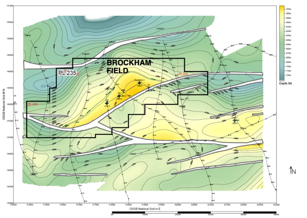
- The Brockham oil field is located on the northern flank of the Weald Basin.
- The structure is a tilted fault block trap, dip closed north, west and east and fault closed to the south. It is producing from a Jurassic Portland sandstone reservoir, buried half a kilometer below the surface. The petroleum system at Brockham is sourced by the Oxford Clay, charging a reservoir of shallow marine sandstones and sealed by the Purbeck Anhydrite.
- Brockham is covered by a network of 2D seismic lines, crossing over the site and wells, which were reprocessed in 2013.
Lidsey Oil Field
Angus Energy operates and holds an 80% interest in the Lidsey field which is on the southern flank of the Weald Basin near Bognor Regis.
- Licence
PL241 (Production Licence) - Licence Area
5.3km2 - Location
Weald Basin, UK, Bognor Regis
- Operator
Angus Energy - Angus Interest
80% - Partners
Terrain Energy 10%, Brockham Capital 10% - Wells
Lidsey 1, Lidsey X2
Originally discovered in 1987 by Carless Exploration when the Lidsey 1 well found oil, Angus Energy drilled a second well, Lidsey X2, in 2017 as a conventional horizontal producer. The Lidsey wells have produced small volumes of crude intermittently in the past, but are currently shut in since there are no commercial options for water disposal available.
The company is evaluating options to bring the field back into production in early 2025.
Lidsey Technical Overview
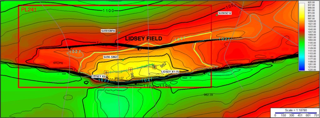
Lidsey field is a footwall fault block structure with a southerly bounding fault and significant Tertiary inversion. It is producing from the Middle Jurassic Great Oolite formation and sourced by the Lias, Kimmeridge & Oxford Clays, charging a carbonate reservoir and sealed by the Oxford Clay.
Lidsey is covered by a network of 2D seismic lines, including Line Lid 001 acquired by Angus in 2021. The seismic was reinterpreted in 2021, allowing for an updated view of the field structure. A reservoir top structure map is shown below.
Balcombe Field Discovery
Angus Energy owns 25% of the Balcombe oil field near Crawley in Sussex with partners Cuadrilla, and Lucas Bolney.
- Licence
PEDL244 - Licence Area
154km2 - Location
Weald Basin, UK, SE of Crawley
- Operator
Angus Energy - Angus Interest
25% - Partners
Cuadrilla Balcombe Ltd. 56.25%, Lucas Bolney Ltd. 18.75% - Wells
Balcombe 1, Balcombe 2Z (to be tested)
The Balcombe discovery was made in 1986 by Conoco, which drilled the vertical Balcombe-1 well and produced 50 barrels of oil per day from a naturally fractured limestone within the Jurassic Kimmeridge Clay Formation.
In 2014 the vertical Balcombe-2 well was drilled to collect a modern dataset over the Kimmeridge Clay Formation. The well was then sidetracked to drill approximately 500 m of horizontal borehole through the naturally fractured limestone reservoir. High initial flow rates subsequently achieved at the nearby Horse Hill 1 well in the same reservoir provided encouragement for Balcombe, however a comprehensive well test has not yet been undertaken.
Angus is planning to carry out an extended well test of the horizontal Balcombe-2z well, when legal challenges have been resolved.